Lashing of containers on deck
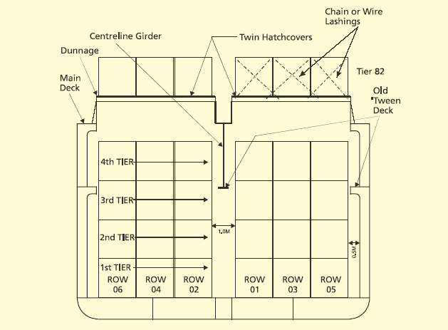
In the early years of containerisation, existing general cargo vessels were converted with the removal of ‘tween decks and the addition of cell guides into the cargo holds. On deck, the hatchcovers were strengthened and fittings added for lashings.
However, the containers on deck were seldom stowed above one high and so were secured to the vessel by ‘traditional’ cargo ship methods.

Typical midship section of an early vessel conversion
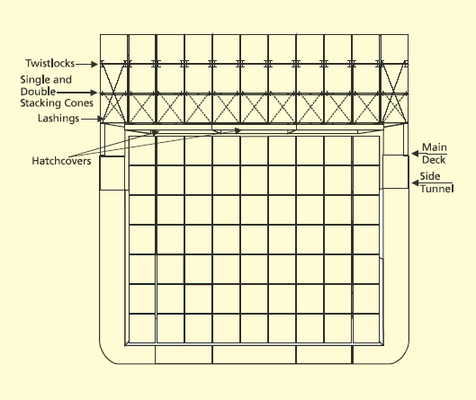
Often seen still trading today, are a few of the ‘first generation’ vessels built during the late sixties and early seventies. These ships were the first to be designed and built as pure container carriers. The holds and hatchcovers were as wide as possible, and container posts were fitted on deck to facilitate loading of deck-stowed containers out to the ship’s side.

Typical midship section through an early generation cellular container vessel
For this generation of vessel, two systems of securing the cargo were common. One relied on the use of twistlocks in conjunction with lashing bars or chains, and the second relied on the use of stacking cones and bridge pieces in conjunction with lashing bars or chains. Gradually, due to the increased utilisation of differing height containers, the second method became redundant and it became common practice to use twistlocks throughout the stow. This method normally allowed containers to be stacked three high and, in some cases, four high if the fourth tier was light in weight or empty.
For first generation vessels, computer technology was not available onboard to speedily calculate dynamic loads acting on container lashings and frames. The shipboard computer (if any) was only used to calculate stresses and stability for the ship itself. Therefore, the shipboard staff would ensure the vessel was lashed according to a lashing plan taken from the lashing equipment manufacturer’s manual, which appeared to assume an ideal stow with respect to the distribution of weight in each stack (the homogenous stack).
With further development in the industry during the 1970s and 80s, the size of containerships continued to grow, with 9-high stowage in holds and 4-high stowage on deck becoming commonplace and the industry began to wake up to the fact that standards in lashing were required. Ships were, at this stage, still supplied with loading computers that continued to calculate a ship’s stability, shear forces, bending and, occasionally, torsion moments. Very few had the capability to calculate dynamic loads on container frames and lashing systems caused by ship motions and wind forces. And so the lashings were still applied throughout the stow in accordance with the manufacturer’s manual. Cargo was being lost overboard even though a properly designed securing system was in place and the cargo was correctly stowed. It became apparent that there was a great deal of ignorance concerning the combined static and dynamic loads acting on a securing system when adverse weather was causing severe ship motions, particularly rolling.
Today, large container ships are being built – known as the ‘post-panamax’ class (too large to transit the Panama Canal) – capable of carrying up to 8,500 TEUs, and small container ships down to coaster/feeder vessels of a few hundred TEUs. But in general terms, by a process of evolution, the lashing systems in use on both types of vessels are very similar. Both have adopted the twistlock and lashing bar/turnbuckle system.
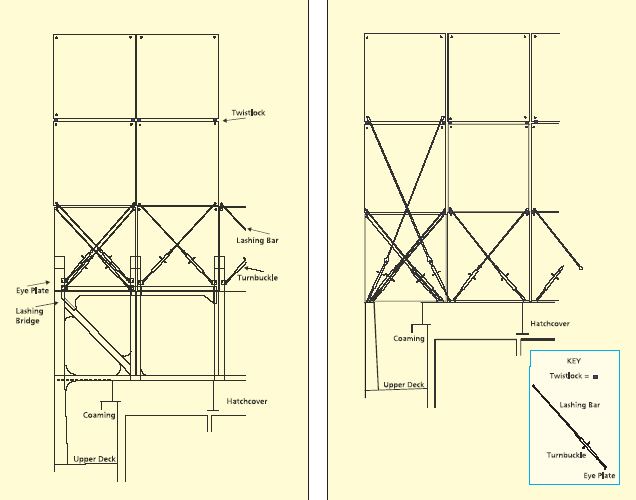
On post-panamax vessels – where among other features the vessel’s large beam results in an unavoidable, relatively large GM (metacentric height), and 6- high stowage on deck is common – the modern practice is for the vessel to be fitted with a lashing bridge; a substantial steel structure running athwartships between each forty foot container bay. This allows the second and third tiers of containers to be secured to the bridge using lashing rods and turnbuckles, whilst the whole stow is secured throughout with twistlocks.

Typical post-panamax lashing bridge arrangement (shown 4-high) – left; Typical container vessel’s hatchcover lashing arrangement – right.
The lashing bridge allows the anchoring points for each stack to be moved higher up the stack, which allows the lashings to be more effective in reducing the tipping moments acting on a stack when a vessel is rolling heavily. However, the practice of fitting the bridges between forty foot bays means that the twenty foot containers can only take advantage of the lashing bridges at one end. So, in effect, the twenty foot stacks have to revert to the limits of a conventional lashing system. This is the case, because the practice of estimating the forces acting on a stack divides the container weight equally between each end of the container. So the weight in each twenty foot container is limited by the capacity of the lashing system at the container end, which does not have the advantage of being secured by a lashing bridge.
On smaller vessels, the whole stow is also secured throughout with twistlocks, and the lowest three tiers are secured to the hatchcover or support post using the lashing bar/turnbuckle combination.
However, since the mid 1980s, naval architects have produced computer programs to calculate the dynamic loads acting on container stacks. Such programs have been designed for use by ships’ officers and container planners. On modern vessels, 5-high and 6-high stowage on deck is common; the use of onboard computers to check the dynamics of the stow in all weather conditions is vitally important for the safe carriage of the cargo. The use of a computer lashing program, together with the IMO requirement for every vessel to carry onboard an approved Cargo Securing Manual, should mean a reduction in collapsed stows and losses overboard, provided the operators maintain the lashing equipment and comply with the requirements of the Manual. The vigilance of ships’ staff is therefore vital to ensure that lashings are applied correctly.


